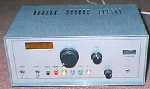
This photo is a HF receiver,
one application of this controller.
1.Intention
Å@Å@I thought to make a small variable step of PLL for VFO of RF receiver.
But total variable range of frequency of the PLL IC is limited usually
amount 4 digits. In order to get high frequency and wide variable range,
we usually use a bias oscillator that modulates output of PLL.
But in this case, the real receive frequency differs from the set
frequency of PLL. This problem confuses us at making RF receiver ourselves.
This controller gives the solution to this problem and a easy operation.
2.Circuit diagram
Using two onechip CPUs, one is display controller and another is PLL
controller. The display controller is the same with the previous introduced
work. The PLL controller supports the both outputs to PLL and LED. Adding
to this, This controls a rotary switch and several push switch for setting
the frequency.
+----------+ +--------+
LED | | | |
control | PIC16C84 | | LED | +---------------------+
unit | LED |-------->| DRIVER |-->| 5 DIGIT SEGMENT LEDs|
| control | | | | |
| | | | | |
---------- -------- ---------------------
|(serial interface)
------------------ | --------------------------------------------------
--------- ----------
|ROTARY | | |
| ENCODER |->| PIC16C84 | ------------------------------
--------- | SW,PLL | | 74HC595 x2 |
--------- | Control |------>| SERIAL INPUT 16BIT LATCH |
| SWITCH |->| | ------------------------------
--------- ---------- | | | | |
------------------------------
PLL control unit | PLL CONTOROL (MC145163) |
| |
------------------------------
3.Functions
(1) Use two onechip CPU PIC16C84, connected each other by one serial line.
The speed of this is about 10kbps.
(2) Use MC145163 for PLL control IC , four digit BCD data is outputted
for this IC. Convert data from serial to parallel by 74HC595.
(3) Display current real receive frequency at five digit LED
(4) Control under switches
Rotary switch : count up/down frequency by rotate
UP : count up the frequency continuously during pushed
DWN : count down the frequency continuously during pushed
SHFT : shift upper/lower two digits for count up/down in order
to first count.
MRD : read preset frequency and directly set that frequency
MRW : write current frequency to memory as the preset frequency
BIAS : change mode to preset bias frequency, MRW terminate this mode
this bias is used for the calculation of differential between
real frequency and local oscillator.
(5) Following the input of rotary encoder, count up/down internal four
digit BCD data. At this count, in order to input of SHFT switch, count
x1 or x100 of the variable step. This mode is switched alternatively.
(6) Output this four digit of BCD data to PLL control IC by the way serial
to parallel converter and latch IC.
(7) Add the bias to this four digit and output this calculated six digit
BCD data to display controller. This bias data is set freely and
written on the EEPROM, so this bias is not erased during power off.
(8) Can save Max 20 preset frequency data in EEPROM area, and reread at
any time. This preset data are overwritten by push the MRW switch.
These preset data is read by pushing the MRD switch circurately
in 20 data.
At the time of power up, No 0 data is reread automatically and preset
the PLL to this frequency.
4.Circuit Schema and PCB ArtWork
The Circuit and ArtWork are edited with CAD HiWIRE II, then download
and braws by HiWIRE II.
Circuit (Brows by HiWIRE)
Artwork (Brows by HiWIRE)
5.Program Source List
The format of this program is suited to MPASM that is standard assembler
of PIC series one chip microcomputer.
Program list(Compressed by LHA)
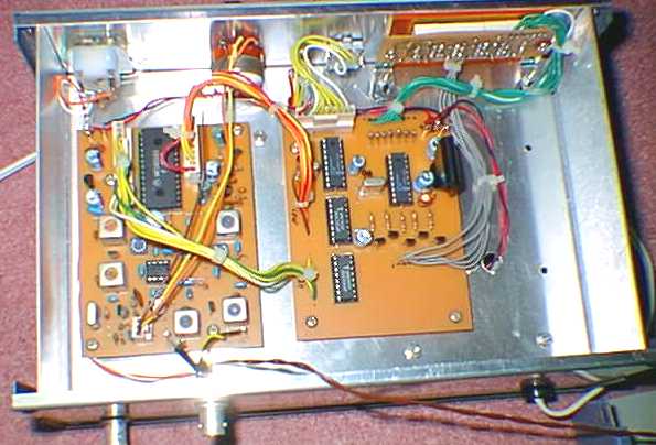
6.Application sample(HF Receiver)
This photo shows upper side of the receiver equipmwnt.
It includes a seven segment LED board at the front panel,
PLL controller board and VFO board at the center panel.
This PLL controller board includes both LED controle unit
and PLL controle unit explained in this document.
This VFO generates 17MHz to 19MHz that is used for the
local oscillator of 7MHz receiver.